Each generation of data hall was laid out to fix the airflow problems of the one before it. The question behind every layout is the same: does the cold air reach the rack intakes, and does the hot air get back to the cooling units without mixing on the way?
This article follows three layouts, from the enterprise raised floor to the fan-wall hall, through a CoolSim model of each, and looks at what each model shows. The metrics quoted are the ones in the CoolSim report, explained in Key Data Center Cooling Metrics.
Click a model image to open it in the 3D viewer.
The machine room
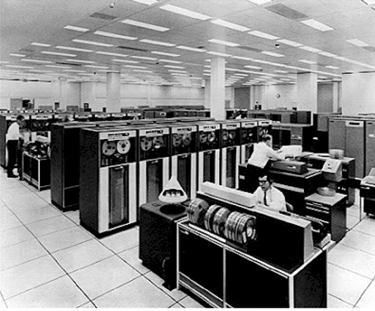
In the mainframe era the computer was the room. Raised floors went in to carry cables, and soon they carried the cooling air as well: cooling units blew into the space under the floor, and perforated tiles let the air out where it was needed. Most of what follows is about that plenum and what happens to air on its way through.
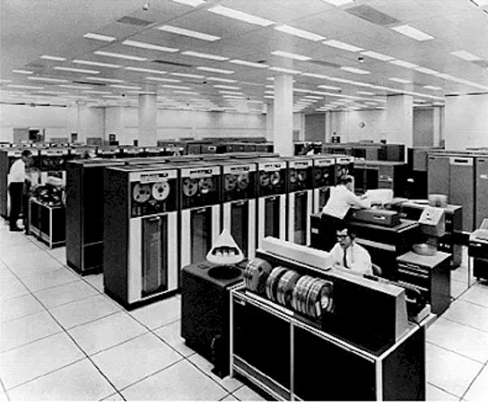
An early mainframe room
The enterprise raised floor
As computing spread through the business, machine rooms filled with racks. Rows were turned to face each other, with cold aisles of perforated tiles in front of the racks and hot aisles behind them, and cooling units stood around the walls.
The first model is a room of that kind: 99 racks carrying about 620 kW, eight cooling units around the perimeter and an 18-inch raised floor, supplied at 65 °F.
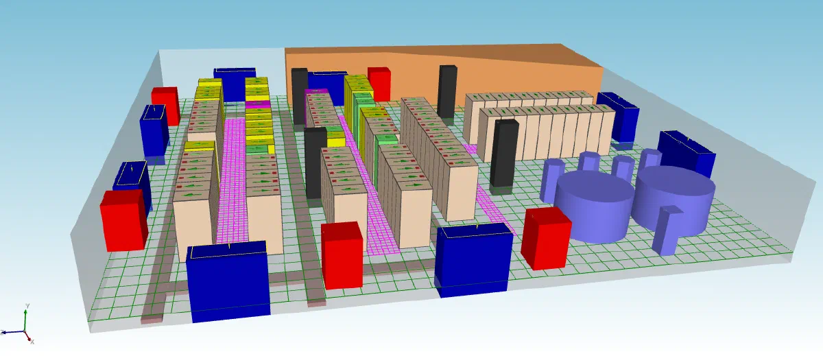
The enterprise room: 99 racks and eight perimeter cooling units (blue) over an 18-inch raised floor
Does every tile deliver the same air? No. The 144 tiles average 786 CFM, but they range from 526 to 950 CFM, so the busiest tile carries 1.8 times the air of the quietest. Close to a cooling unit the air under the floor moves fast and its static pressure is low, so the nearest tiles get less. Farther out the air slows, its pressure recovers, and the tiles toward the middle of the room get more.
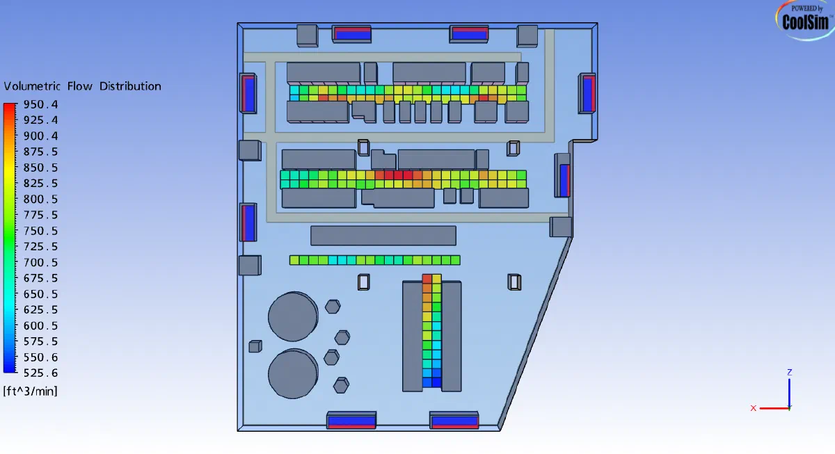
Airflow through each perforated tile, from 526 to 950 CFM
Is the cooling air reaching the racks? In total, yes. The cooling units move almost exactly as much air as the racks draw, and RTI is 100%. Yet RCIHI is 92%, so some intakes are above the recommended maximum. The pathlines show why the totals balance anyway. Some tile air rises over the racks and returns to the cooling units without passing through equipment. When supply and rack airflow are equal, every cubic foot that bypasses the racks is replaced at an intake by a cubic foot of recirculated exhaust. Net, the two cancel; locally, they are what put intakes over the limit.
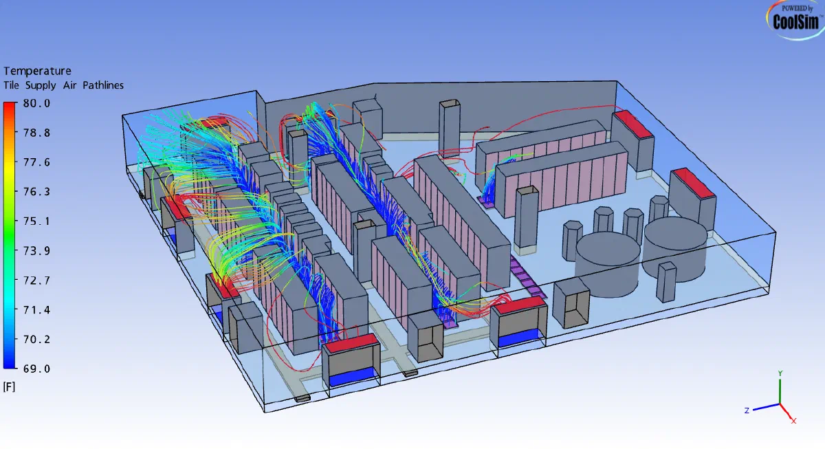
Pathlines from the tiles, colored by temperature. Some tile air passes over the racks and back to the cooling units
The usual remedies are to rebalance the tiles, with less open area where the flow is high and more where it is low, and to contain the cold aisle so that tile air has nowhere to go but through a rack. Both are changes to try on the model before making them on the floor.
The contained colocation hall
Multi-tenant halls grew to hundreds of racks, and efficiency became a design goal in its own right; The Green Grid introduced PUE in 2007. Containment became common: close off one aisle so that hot and cold air cannot mix over the tops and ends of the rows.
The second model is a hall of that kind: 807 racks in hot-aisle-contained rows, about 3.8 MW of IT load, 13 cooling units along the long walls and a 30-inch raised floor, supplied at 70 °F.
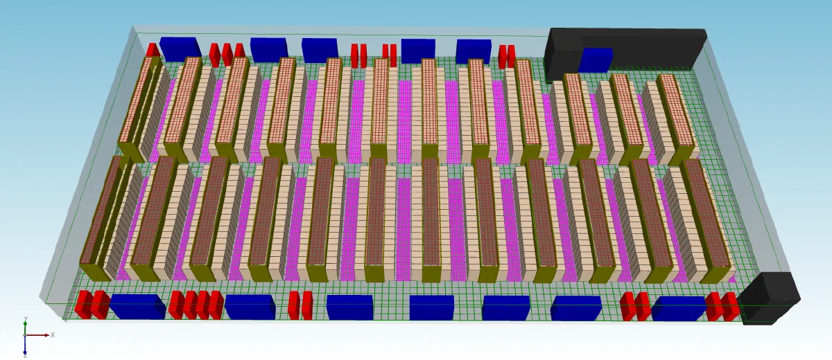
The colocation hall: 807 racks in hot-aisle-contained rows, 13 cooling units (blue) and 22 PDUs (red)
By the room metrics this hall is in good shape. RCIHI is 99.9%, so almost every intake is within the recommended range. RTI is 93%: the cooling units move about 520,000 CFM against the racks’ 480,000, and the difference bypasses.
What does containment leave unsolved? The floor. Supply air from units on opposite walls meets under the middle of the hall and swirls in the plenum.
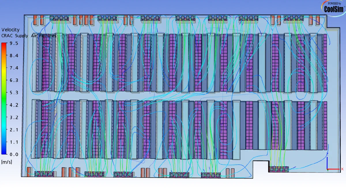
Supply air pathlines from the cooling units, colored by velocity. Jets from opposite walls meet and swirl under the floor
The 807 tiles average 640 CFM, but they range from about 1,710 CFM down to −270 CFM. A negative flow means the tile runs backwards, drawing room air down into the floor. That happens where the air in the plenum moves fast enough that its static pressure falls below the room’s.
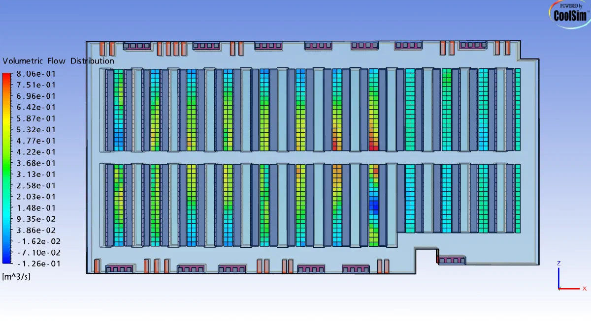
Airflow through each tile, from about −270 CFM (air drawn down into the floor) to 1,710 CFM
Containment decides where the air goes after it leaves a tile. It does nothing about how the plenum divides the air among the tiles. With the hot aisles contained, the rest of the hall is one large cold space, so an intake beside a starved tile still draws cold air, which is likely why RCI stays near 100% despite the spread. The bypass flow still has to be paid for in fan energy.
The fan-wall hall
The largest halls drop the raised floor. Walls of fans along the sides of the hall blow supply air across a slab floor, and the hot aisles are contained and returned through the ceiling.
The third model is a hall of that kind: 720 racks at 14 kW each, about 10 MW in all, in hot-aisle-contained pods, with fan walls on both long sides, supplied at 70 °F.
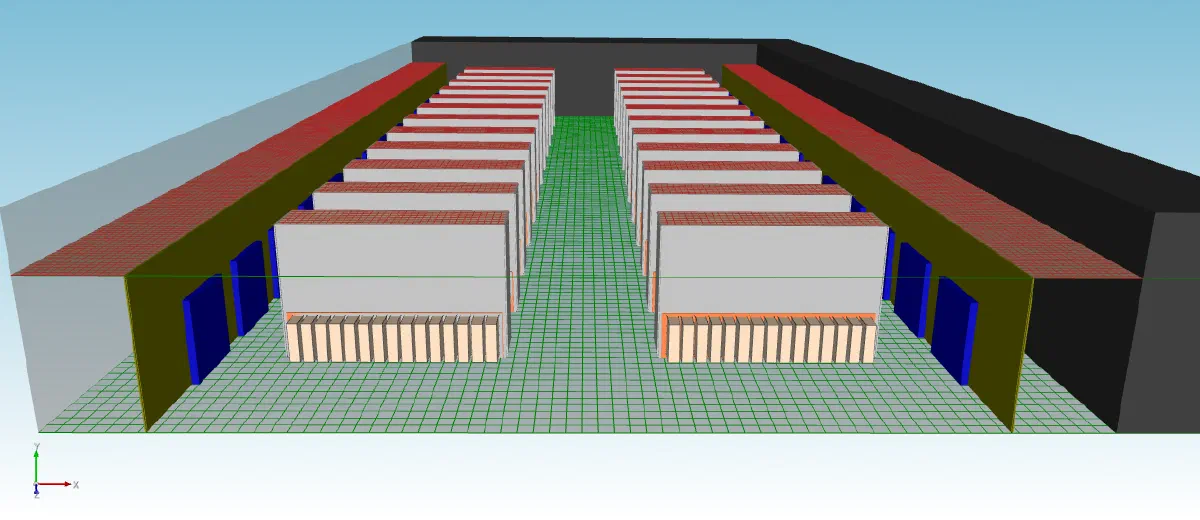
The fan-wall hall: 720 racks in contained pods, fan walls on both sides, slab floor
By the room metrics this hall is in good shape as well: RCIHI and RCILO are both 100%, and RTI is about 99%.
Where is the margin thin? At the ends of the pods. To reach the middle of the hall, the supply air has to move fast. At 6 feet above the floor it reaches about 480 ft/min where it enters the cold aisles at the ends of the pods.
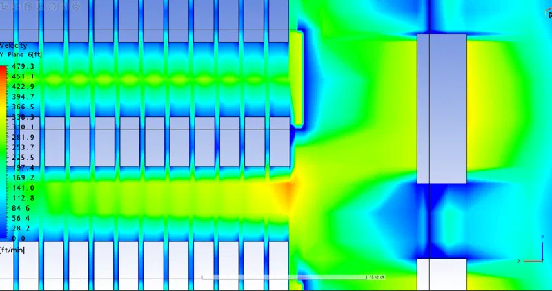
Air speed 6 ft above the floor, up to about 480 ft/min where supply air enters the cold aisles
Fast air has low static pressure. The pressure map shows the contained hot aisles sitting about 0.01 to 0.02 inches of water above the cold aisles, with the lowest cold-side pressure near the fan walls.
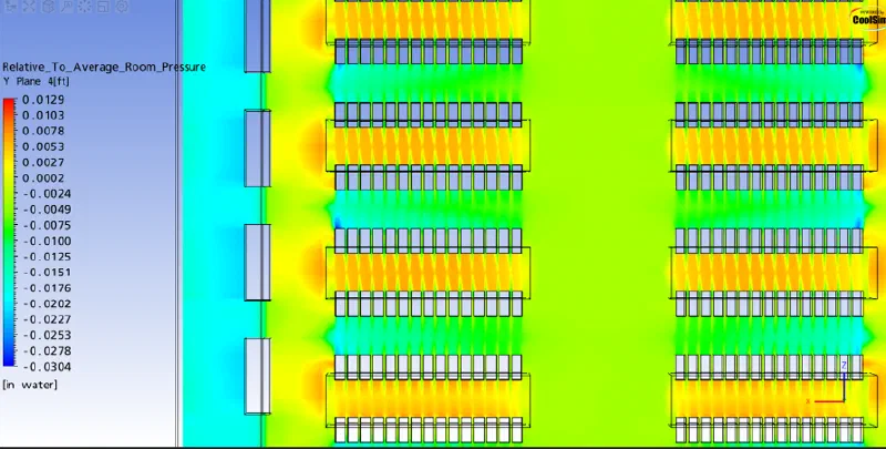
Pressure relative to the room average, 4 ft above the floor. The contained hot aisles (orange) sit above the cold aisles (green)
A model shows leakage only through the gaps it includes. What this one shows is the pressure difference that would drive it. In a real hall, any path between the two sides (rack rails, missing blanking panels, joints in the containment) carries hot air toward the intakes, and carries the most near the fan walls, where the difference is largest. Across the pod, the hot aisle runs from about 88 °F at one end to 99 °F at the other, so what leaks depends on where the gap is.
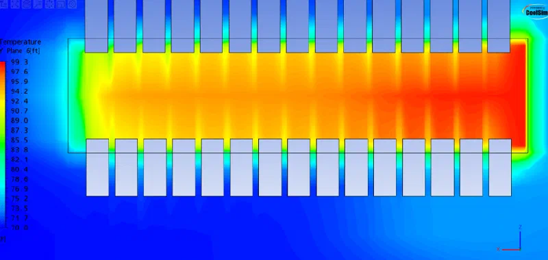
Temperature 6 ft above the floor across one pod. The hot aisle runs from about 88 °F to 99 °F; the cold side stays near the 70 °F supply
Denser racks and liquid cooling
Rack densities keep rising, and more of the heat now leaves by liquid, through rear-door heat exchangers or cold plates on the chips. A liquid-cooled rack still puts part of its heat into the room (fans, power supplies, and whatever the liquid loop does not capture), and that heat still has to reach a cooling unit. In a CoolSim model you enter the share of each rack’s heat removed by liquid, and the model carries the rest as heat to air.
What the three models have in common
Each layout fixed the airflow problem of the one before it, and each model still shows one left over. In the enterprise room it is bypass and recirculation that cancel in the totals. In the colocation hall it is tiles delivering anything from 1,710 CFM to less than nothing. In the fan-wall hall it is a pressure difference across the containment. None of these shows in a room total, and two of the three rooms score close to 100% on every metric. They show at individual tiles and intakes, which is what a CFD model resolves.
For how such a model is built and solved, see What is CFD?.