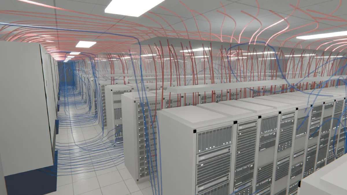
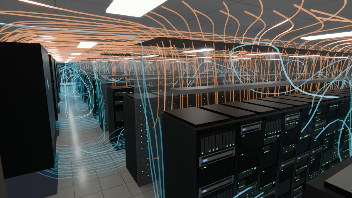
Containment puts a physical barrier between the cold supply air and the hot exhaust. Done well, it turns a room where the two streams mix into one where each rack sees supply air. Done badly, or run past its airflow limit, it still helps, but the hot spots move to the places the seals fail.
What it separates
In an open room, supply air that never reaches a rack goes straight back to the cooling units (bypass), and exhaust that curls around a rack gets drawn back into its intake (recirculation). Bypass wastes fan energy and chilled air. Recirculation makes hot spots.
Cold-aisle containment closes the cold aisle with doors and a roof, so the only way for supply air to leave is through the racks. Hot-aisle containment does the reverse: it encloses the exhaust and ducts or lets it return to the units without touching the room.
The Return Temperature Index (RTI), the racks’ airflow as a share of the units’ airflow, summarizes the net effect. Below 100% the units supply more than the racks draw, and the extra bypasses. Above 100% the racks draw more than is supplied, and the difference is recirculated exhaust. We cover it, with RCI, in the cooling metrics article. RTI is a net number: two rooms with the same RTI can have very different hot spots, and containment is what decides which one you get.
Published field data gives a sense of the size. Schneider Electric’s White Paper 153 reports that in a traditional uncontained raised-floor room, more than 50% of the supplied cold air can bypass straight back to the cooling units through leakage paths. It estimates that containing and sealing those paths can raise cooling capacity by about 20% or more, by letting the exhaust come back hotter [1].
A test room, open and contained
We tested the effect in a synthetic room: 30 by 28 by 10 ft with a 2 ft raised floor, two downflow cooling units supplying 65 °F (18 °C) air, and twelve 10 kW racks in two rows around a shared cold aisle. The airflow is the same in every layout, so only the containment changes. The racks draw about 15,180 CFM against 16,000 CFM supplied, an RTI of 95%. (This RTI is calculated from the rack heat and a 25 °F rise; the open-hall run uses the same room.)
| Layout | Hottest inlet | Racks over 80.6 °F (27 °C) | Racks over 89.6 °F (32 °C) |
|---|---|---|---|
| Open hall | 106.3 °F (rack R6) | 12 of 12 | 9 of 12 |
| Cold-aisle containment | 79.9 °F (R1) | 0 of 12 | 0 of 12 |
| Hot-aisle, 5% end-cap leak | 92.3 °F (R12) | 2 of 12 | 1 of 12 |
| Hot-aisle, 10% end-cap leak | 90.5 °F (R12) | 3 of 12 | 1 of 12 |
Table 1
Same room, same racks, same cooling units, four layouts. 80.6 °F and 89.6 °F are the ASHRAE recommended and allowable limits for class A1 equipment. The hot-aisle layouts leave 5% and 10% of the end caps open.
Open, every rack is over the recommended limit and nine are over the allowable one. Cold-aisle containment brings the aisle to an average of 66.3 °F (19.1 °C), and no rack is over. Both rooms have the same RTI.
Hot-aisle containment did worse in this room, and the reason is layout, not the idea. It needs supply tiles along both outer sides of the room, so cold air reaches the rack fronts from outside the enclosure. The far end, by racks R6 and R12, had no tile and no return path, so the leaked air pooled there at up to 97.4 °F (36.3 °C).
Where containment leaks
The seals fail in predictable places:
- Gaps around doors and between the roof and the rack tops.
- Gaps between racks.
- Missing blanking panels, so air passes through the rack’s own unused slots.
- Cable cutouts in the floor and rack tops.
- End-of-row panels and doors.
- Openings in the floor under the aisle.
A U.S. Department of Energy bulletin lists the same culprits, naming air leaks, cable penetrations and missing blanking plates, and recommends brush-type seals around cabling [2]. Blanking panels and cable seals cost little; they are the first things to check.
Why row ends run hottest
Row ends are the most exposed part of an aisle. The end doors and end panels are the largest seams, and a rack at the end has one side open to the room.
In the test room, the warmest inlets in the contained layouts sat at the row ends: R1, R6, R7 and R12, next to the end doors. The same shows up in our airflow management white paper, where 118 of the 128 racks over limit in the test hall sit in the outer thirds of rows, toward the walls.
The margin matters too. The cold-aisle layout’s 79.9 °F peak is 0.7 °F under the limit. At a finer mesh, R1’s hot spot is 84.1 °F, in a streak about 1% of the intake face wide, while averages stay within 0.9 °F. Another run, with a second-order scheme, put R1 at 81.0 °F. So containment held the room, but the end rack is the one to watch, and the figure should be read to within a few degrees, not a tenth.
A second point from the same study: halving the end-cap leak did not reliably lower the worst rack. We have not confirmed why. Closing one leak can shift where the air goes without lowering the peak.
When the room goes negative
Containment depends on the units supplying at least as much air as the racks draw. When they do not, the contained aisle goes negative: the racks pull from the aisle faster than the units fill it, and the shortfall comes in through every leak in the seal.
We ran this case on the same test room by raising the heat in one row to 40 kW, all air, so the racks wanted 37,950 CFM against 16,000 CFM supplied, an RTI of 237%. The cold aisle filled with exhaust air. All 12 racks went over the recommended limit, the hottest inlet reached 130.6 °F (54.8 °C), and only a pocket in front of three racks stayed cool. This is a best case, because the model holds the units at 65 °F at any load. A real overloaded unit would deliver warmer air.
Containment does not change how much air the racks draw. It only keeps that air from being wasted. If the room is short of air, no seal fixes it.
What to check first
- Compare total rack airflow to total unit airflow, with a unit down.
- Seal what is cheap: blanking panels, cable cutouts, rack gaps.
- Look at the row ends.
- If the answer isn’t clear, model the room.
Sources
- Lin, Avelar and Niemann, “Implementing Hot and Cold Air Containment in Existing Data Centers,” Schneider Electric White Paper 153.
- U.S. DOE Federal Energy Management Program, “Data Center Airflow Management Retrofit,” Technology Case Study Bulletin, September 2010.
For the full treatment of containment, return paths and what they do to energy use, see our airflow management white paper, or contact us about a study of your room.