Rooftop CRAC Units
What is a Rooftop CRAC Unit?
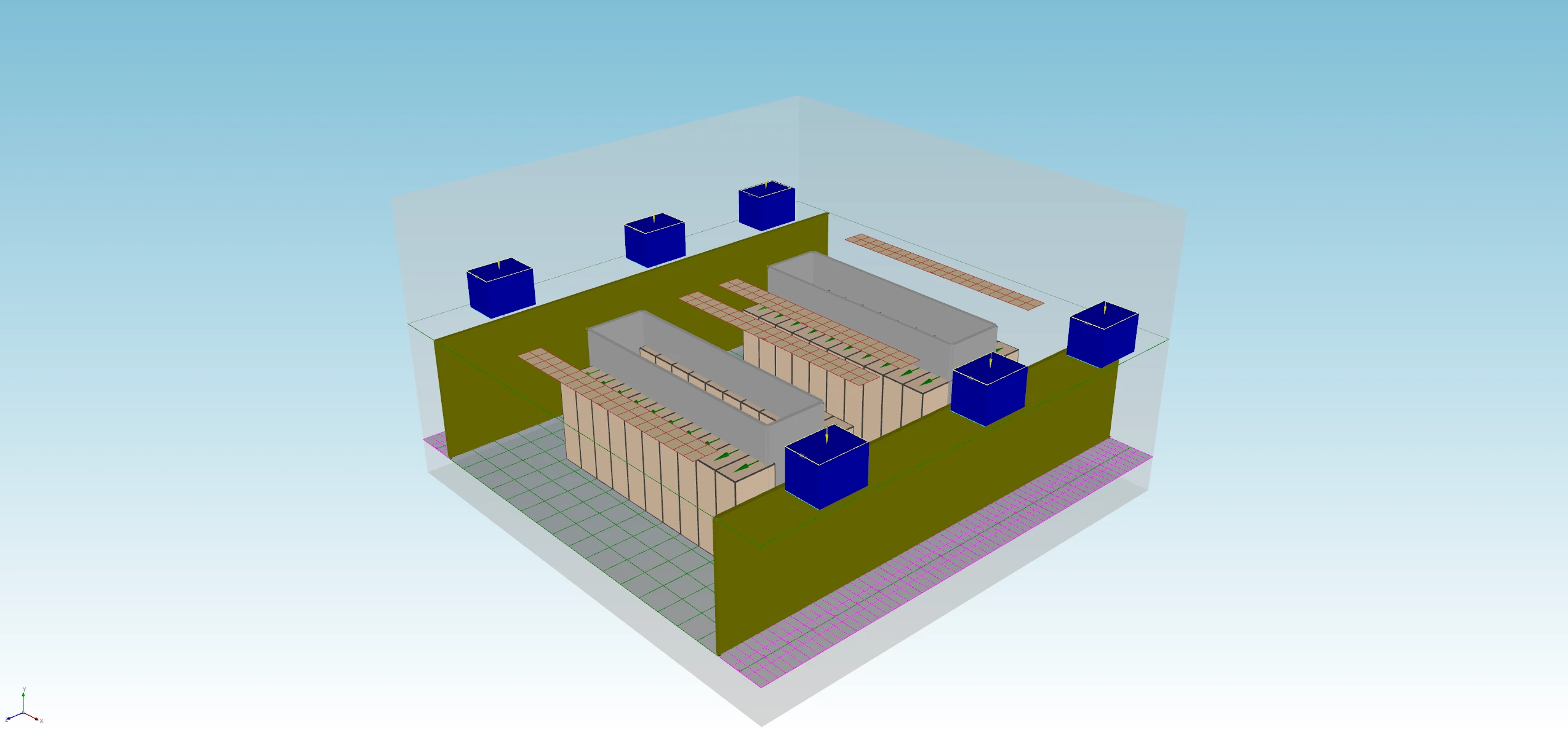
A Computer Room Air Conditioner (CRAC) is a self-contained unit that cools, dehumidifies, and filters the air in a data center. In a rooftop configuration, CRAC units are mounted on or above the roof of the data center room and deliver conditioned air downward through the ceiling or via ductwork. The warm return air rises naturally and is drawn back up into the units, creating a top-down supply airflow pattern. This is the configuration shown in the image above: supply air enters through ceiling diffusers (salmon-colored tiles), passes through the hot and cold aisles, and warm exhaust air exits the top of the server racks back toward the rooftop units.
Rooftop units offer several practical advantages: no raised floor is required, installation is outside the occupied data center space (reducing maintenance disruption), and the design scales well for small-to-medium facilities. The main challenge is that the longer air travel path from ceiling to rack inlet increases the risk of hot and cold air mixing before reaching the equipment—a key phenomenon CoolSim helps you evaluate.
Modeling a Rooftop CRAC Design in CoolSim
Step 1: Define the Room Geometry
Start by entering your room dimensions in the CoolSim Room Setup panel. For rooftop designs, set the ceiling height accurately—this directly affects the supply air’s travel distance and momentum when it reaches rack level. If the room has a suspended ceiling or plenum, model that as a separate zone or account for its depth in your ceiling height input.
Step 2: Place the CRAC Units
In CoolSim, add each rooftop CRAC unit as a ceiling-mounted supply device. For each unit you will need to specify:
- Airflow rate (CFM or m³/hr) — from the manufacturer datasheet
- Supply air temperature (°F or °C) — typically 55–65°F (13–18°C)
- Supply direction — downward for ceiling-mounted units
- Footprint / diffuser location — matched to your ceiling tile grid
In the image above, the salmon-colored ceiling tiles represent CRAC supply diffusers. Each cluster corresponds to one rooftop unit’s supply zone. Spreading diffusers evenly over the cold aisle columns is the most effective starting configuration.
Step 3: Define the IT Load and Rack Layout
Add server racks in CoolSim using the rack placement tool. For each rack, enter:
- Total IT power (kW) — the actual or nameplate load
- Rack height (U) and footprint
- Airflow direction — front-to-back (most common)
Arrange racks in the hot aisle / cold aisle pattern visible in the image above: racks face each other across a shared cold aisle so they draw cool supply air from one side and exhaust hot air into a shared hot aisle on the other. The gray rectangular volumes in Figure 1 represent containment panels or blanking structures that help enforce this separation.
Step 4: Set Boundary Conditions and Run
Before running the simulation, verify:
- Total CRAC airflow is sufficient for your IT load. A common rule of thumb is 1 CFM per 1 watt of IT load, though CoolSim will tell you if this is inadequate.
- Room inlet and outlet pressures are set appropriately (CoolSim defaults are suitable for most sealed room models).
- All walls, floor, and ceiling are assigned correct thermal boundary conditions.
Run the simulation. CoolSim will typically converge in a few minutes for room-scale models at this complexity.
Interpreting the Results
CoolSim produces temperature and airflow maps that let you assess cooling effectiveness across the entire room. Focus on these key outputs:
- Rack inlet temperature map: Check that all rack face temperatures are below your equipment’s maximum inlet spec (ASHRAE A1 class: ≤59°F / 15°C; A2: ≤80°F / 27°C). Any red zones flag equipment at risk.
- Return air temperature: The temperature at the CRAC return should be substantially higher than supply—typically 15–25°F ΔT. A low ΔT means cold air is short-circuiting back to the return without picking up heat from the racks.
- Airflow velocity vectors: Look for stagnant zones or recirculation patterns in the cold aisle. These indicate areas where supply air is not reaching equipment effectively.
Next Steps
Once your baseline model is converged and validated against your room layout, consider:
- Running a partial-load scenario (e.g., 50% IT load) to verify cooling remains effective during low-utilization periods
- Testing CRAC unit failure modes—remove one unit from the model and check whether redundant units maintain safe rack inlet temperatures
- Exporting temperature maps and airflow reports from CoolSim to share with your facilities or colocation team
CoolSim’s value in rooftop CRAC designs lies in making the invisible visible: airflow patterns that seem intuitive on paper often behave very differently in practice. Running the simulation before finalizing your layout is the most cost-effective design review you can do.
This article is part of the CoolSim Knowledge Base. For questions, contact Applied Math Modeling, Inc.