Today a data hall model and a campus airflow model each assume the other’s answer. The hall model assumes the cooling plant delivers its design supply temperature, whatever the weather. The site model assumes how much heat each condensing unit or chiller throws out. On a hot, windy day neither holds.
A condensing unit or air-cooled chiller that breathes its neighbor’s discharge takes in air hotter than the day. It loses capacity and needs more compressor power, and the extra power is more heat on the roof. If it loses enough, the air it supplies to the racks warms up, and the racks get hotter. Neither model on its own can see that loop.
Rack to rooftop solves the hall, the site and the cooling plant together, and passes the answers between them until they agree.
How the loop works
The heat goes up to the roof, and the roof decides how well it comes back down.
The hall's heat leaves through the condensing units on the roof. What those units take in depends on the wind and on their neighbors, and that sets the supply air they can deliver to the racks.
- The hall is solved at the plant’s design supply temperature: how much heat each cooling unit removes, and the temperature at every rack inlet.
- The plant turns that heat and the design outdoor temperature into the heat each condensing unit or chiller rejects, and the compressor power it takes.
- The site is solved in your wind case, with each unit rejecting that heat: the temperature of the air each one actually takes in, including any of its neighbors’ discharge.
- The plant runs again at that entering air: the capacity it really has, the compressor power, and the supply temperature it can hold.
- Whatever moved is solved again. If the supply temperature moved, the hall is solved at the new supply. If the heat rejected moved by more than 2%, the site is. The loop stops when the supply agrees within 0.2 °F (0.1 °C) and the heat within 2%.
Each pass starts from the last one’s answer, and all three models stay in one job, so a pass that changes little is quick. When the hall is solved again, each cooling unit’s supply moves about a third of the way to the plant’s new answer, not all of it: two units near their limit trade load between them, and a full step makes each pass overshoot the last.
The racks and the chillers
In a hall cooled by chilled water, three temperatures tie the racks to the chillers: the air the racks take in, the air the cooling units supply, and the chilled water. Rack to rooftop follows all three.
Three temperatures tie the racks to the roof.
The racks take in the supply air, the cooling unit makes the supply air from the chilled water, and the chiller on the roof makes the chilled water from the outdoor air it takes in.
The racks set the chilled water. The supply air has to be cold enough that the hottest rack inlet stays under its limit, and each cooling unit’s coil needs water about 5 °F (3 °C) colder than the air it supplies. So the rack that runs hottest, because it pulls in exhaust over the top of its row or sits where the floor delivers too little air, holds the chilled water colder for the whole plant. The hall model shows how far the supply could rise before the hottest rack reaches its limit, and which rack gets there first.
Warmer chilled water is cheaper to make. On the reference chiller data our plant model uses, from EnergyPlus, each 1 °F warmer chilled water takes about 1.6% off an air-cooled chiller’s compressor power and 2.6% off a water-cooled chiller’s, and adds 2 to 3% to its capacity.
The roof sets what the chiller can do. An air-cooled chiller is rated on the day’s air, but it works on the air it takes in. Near a 95 °F (35 °C) design day, each 1 °F of a neighbor’s discharge in its intake costs about 1.3% more compressor power and 0.5% of its capacity. Ten degrees of recirculation costs about 14% more power and 5% of its capacity, and the extra power is more heat on the roof. A cooling tower that takes in its own plume, or a neighbor’s, sees a higher wet bulb and sends warmer water to its chiller.
A chiller works on the air it takes in, not on the day's air.
The wind carries one chiller's warm discharge into its neighbor's coil. Ten degrees of it costs the neighbor about 14% more compressor power and 5% of its capacity.
And the chiller sets the racks. Usually a chiller that loses capacity just works harder, and the supply holds. When it can’t, the chilled water leaves warmer than its setpoint, the supply air follows it, and every rack inlet on that plant rises with it. The plant reports the supply it can actually hold, and the hall is solved again at that supply. Our first test shows a plant that passes its design check losing its margin this way.
When the chiller can't hold its setpoint, the racks feel it.
The wind folds the chiller's discharge back into its own coil. If it loses enough capacity, the chilled water leaves warmer than its setpoint, and the supply air and every rack inlet on that plant follow it.
What the plant model does not show yet
- Chilled water warmer than 50 to 55 °F. The reference data ends at 50 °F (10 °C) chilled water for the air-cooled chiller and 55 °F (12.8 °C) for the water-cooled one, and above that the model holds the chiller where the data ends. So today it shows no saving from raising the supply air past about 55 °F (air-cooled) or 60 °F (water-cooled), which is colder than most halls already run.
- A cooling tower breathing its own plume. On the reference water-cooled plant the condenser water reaches the top of the chiller’s data at any wet bulb from 60 to 80 °F, so a few degrees of extra wet bulb changes nothing the model reports.
What it answers
- Does the cooling still hold the supply temperature the racks need on the design day, in the wind that sends the most discharge back into the intakes?
- Which condensing unit or chiller limits the room, and by how much?
- What does the recirculation cost in capacity and in compressor power?
- How warm can the chilled water run? How far the supply air can rise before the hottest rack inlet reaches its limit, and which rack holds it down.
- Does a site change help the racks? A condensing unit moved, a screen wall added, raised or taken away: each is judged by the hottest rack inlet, not only by the temperature at the intake.
- How much more IT load can the room take before the supply temperature starts to drift?
Our first test: a plant with 2% to spare
This is a test model we built, and it is deliberately small. We sized its plant the way a design check does, on a 95 °F (35 °C) design day, and then solved the hall, the roof and the plant together on that same day.
- The hall: 24 × 20 ft (7.2 × 6.0 m), 8 racks of 5 kW in a contained cold aisle, 40 kW in all, with a raised floor and a ceiling return. Two DX cooling units supply 75.2 °F (24 °C) air, one for each half of the room.
- The plant: each cooling unit has its own condensing unit on the roof. At 95 °F entering air each has about 20.5 kW of cooling for the 20 kW its half of the hall needs: 2 to 2.5% to spare.
- The site: the building in a 9 mph (4 m/s) wind from the west on the 95 °F day. The two condensing units sit side by side on the roof, 3 ft (1.0 m) apart. We solved the roof open and with an 8 ft (2.4 m) noise screen around the units, 4 ft (1.2 m) clear of them, and then looked for a fix.
The design check passes. At the 75.2 °F supply the hottest rack inlet is 77.4 °F, 3.2 °F under ASHRAE’s recommended 80.6 °F (27 °C). That is what a hall model on its own reports: it assumes the plant holds its setpoint, and on paper it does.
On the open roof it still holds. The wind carries a little of the first unit’s discharge into the second, so the units take in 95.5 °F and 96.4 °F air. The second unit’s spare capacity falls from 2.0% to 1.3% and the plant draws 1.6% more compressor power, but both units hold 75.2 °F, and the hall did not need solving again.
Behind the screen it does not. The screen holds the units’ discharge around them, and they breathe it back: the first takes in 102.6 °F air and the second 105.6 °F, 7.6 and 10.6 °F above the day. At that air neither has the capacity its half of the hall needs, so the plant cannot hold 75.2 °F. The supply rises until the warmer return gives the cooling units enough capacity to carry the 40 kW, and settles at 77.4 °F from the first unit and 77.8 °F from the second. The compressors draw 13.6% more power than the design check says, and the hottest rack inlet rises from 77.4 to 79.7 °F. That is still under 80.6 °F, but by 0.9 °F, not 3.2: the screen spends 72% of the margin the design check shows. The loop took ten solves to agree: the hall at the design supply, the site twice, then the hall seven more times, each at a supply a little warmer than the last.
Raising the screen gets it back. We lifted the same screen 2 ft (0.6 m) off the roof and kept its top at 8 ft, so the wind can pass under it. The units take in 96.4 and 98.2 °F air, both hold 75.2 °F, and the hall did not need solving again: the hottest rack inlet is back to 77.4 °F, with the full 3.2 °F of margin. The compressors draw 3.8% more power than the design check says, against 13.6% behind the full screen. The loop agreed in two solves. It holds with little to spare: the second unit is left with 0.3% of its capacity, about 0.6 °F more entering air before it starts to give.
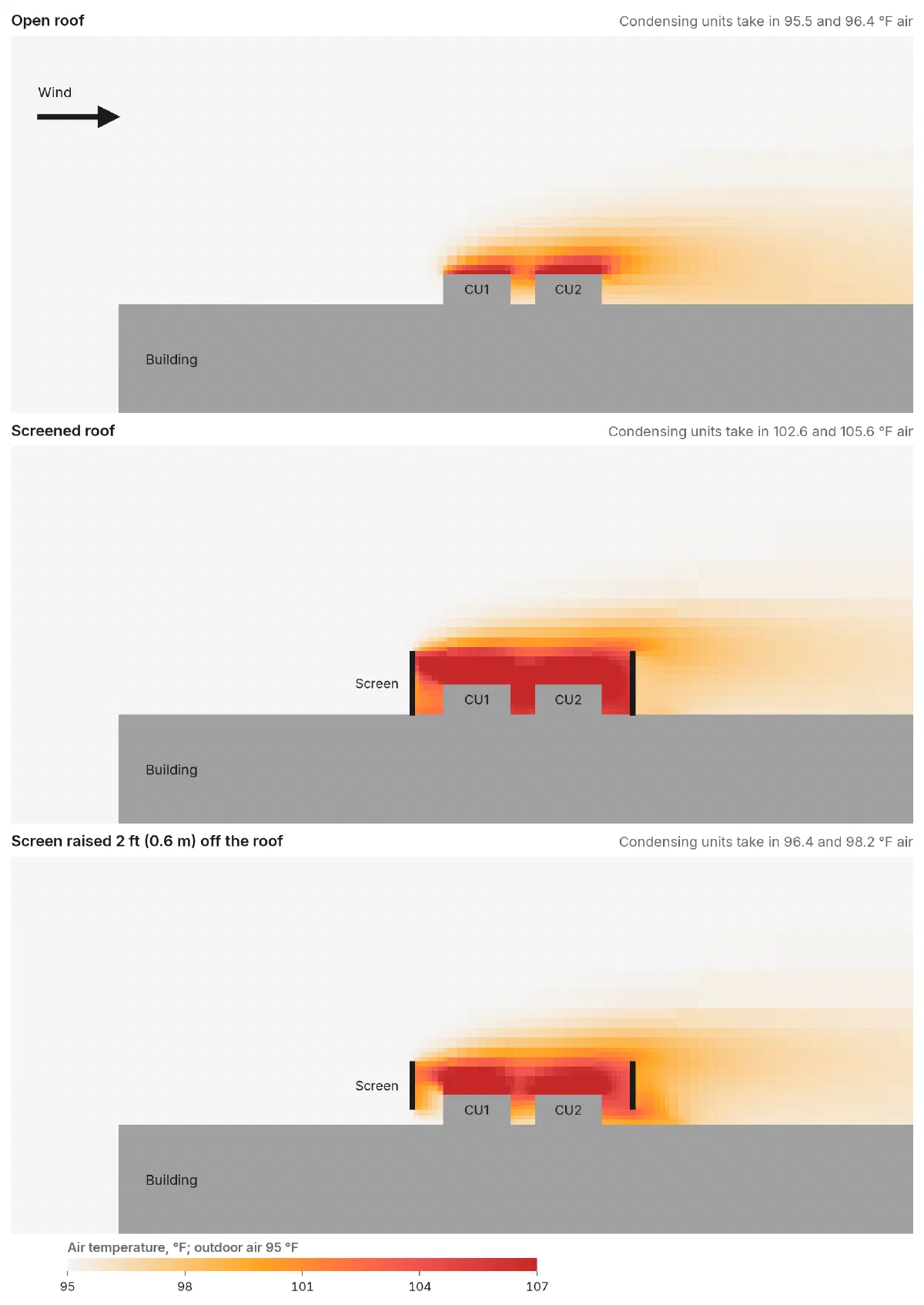
The roof from the side, cut through both condensing units, wind from the left. Open, the wind carries the discharge away, and the units take in 95.5 and 96.4 °F air. Behind the screen it stays around them, and they take in 102.6 and 105.6 °F. With the screen raised, the day’s air comes in under it, and they take in 96.4 and 98.2 °F.
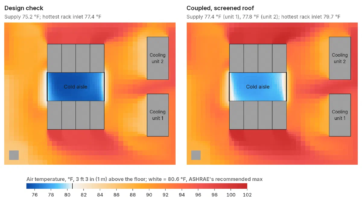
The hall from above, 3 ft 3 in (1 m) off the floor. White is ASHRAE’s recommended 80.6 °F; blue is under it. A hall model on its own stops at the left-hand plan. Solved with the roof and the plant, the cold aisle runs 2 to 3 °F warmer and the hottest rack inlet comes within 0.9 °F of the limit. Cooling unit 1 is served by CU1, cooling unit 2 by CU2. Racks, cooling units and a column in grey.
Neither model alone sees it. The hall model assumes the 75.2 °F supply and reports 3.2 °F of margin. A site model shows the condensing units taking in 102 to 106 °F air, but not what that does to the racks. The plant passes its design check at 95 °F. Only the three solved together, until they agree, show that this screen spends 72% of the hall’s margin on the design day and costs 13.6% more compressor power. And only that loop can judge a fix by the number that decides it: raising the screen takes 6 to 7 °F off the condensing units’ air, and what that buys is 2.3 °F back at the hottest rack inlet.
What the test did not show
- Two other fixes, on the roof only. We solved two more screens on the roof alone, not through the full loop. Moved out to 8 ft (2.4 m) from the units, it helped only partly: they took in 100.3 and 99.7 °F air, and at that air the plant alone still lets the supply slip a few tenths of a degree. A screen half as tall, 4 ft (1.2 m), did as well as the raised one, 96.5 and 97.9 °F, but it is half the screen. We have not solved a taller discharge or a bigger plant.
- What the fix costs in noise. Air that comes in under a raised screen lets sound out the same way, and a lower screen blocks less. We have not worked out how much either gives up.
- No chillers. The test plant was DX. The plant model covers air-cooled and water-cooled chillers and dry coolers, but no chilled-water hall has been through the loop yet.
- The return air’s humidity is held at 30%. At a fixed relative humidity a warmer return carries more moisture, which gives a DX coil more capacity, so the plant here wins back more as the hall warms than a real one would. The real drift is likely larger.
- One wind. 9 mph from the west only. We have not looked for this roof’s worst direction.
- The site mesh is not fully settled at the screen. Between our two finest site meshes the second unit’s air moved from 104.4 to 105.5 °F behind the screen and from 97.7 to 98.2 °F with it raised; on the open roof it moved by less than 1 °F. Raising the screen took 6 to 7 °F off the units’ air on both meshes. The raised screen’s 0.6 °F to spare is about what one more refinement could move, and even if it is used up, the supply would drift a few tenths of a degree, not the 2.2 to 2.6 °F behind the full screen. The page shows the finer mesh.
- The hall mesh is coarse: 6 in (15 cm) cells. A study refines it until the hottest rack inlet stops moving.
- Dry-bulb temperature only. Humidity, which matters for evaporative cooling and cooling towers, comes next.
What we need from you
- The hall: a CoolSim model of the room, or the drawings to build one.
- The site: a site plan with the buildings, screen walls and every condensing unit, chiller and generator.
- The plant: which cooling units each condensing unit or chiller serves, and each one’s capacity and power at different entering-air temperatures and, for a chiller, different chilled-water temperatures; the supply-air and chilled-water setpoints; and each cooling tower’s design wet bulb and approach. Manufacturer data sheets are fine.
- The design day and the wind: the design outdoor temperature, and the wind directions you’re worried about.