Introduction
Most data centers carry at least one more cooling unit than the load needs, so that a unit can fail, or be taken down for service, without the racks running hot. This N+1 margin is usually checked with a sum: the airflow and capacity of all the units less one, against what the racks need. The sum treats every unit as interchangeable. The racks do not. A rack takes in whatever air reaches its inlet, and a unit on the far side of the room does little for it.
An earlier CoolSim paper on cooling redundancy, WP108 [2], put the question this way: which units “can safely be turned off without causing hot spots on some of the rack inlets? More importantly, which one(s) cannot?” It tested four of its 26 units. In this paper, CoolSim is used to switch off each of the 18 cooling units in a 234-rack room, one at a time, and then to test two ways of making up the air a lost unit supplied.
Problem Description
The room (Figure 1) is the one studied in WP110 [3]: 124 ft by 57.5 ft, with a slab floor, an 11.75 ft ceiling and a 21 in. plenum above the ceiling. It holds 234 racks at 4 kW each, 936 kW in total, in 14 rows that form seven hot aisle pairs. Each hot aisle is enclosed, and its exhaust leaves through grilles into the ceiling plenum.
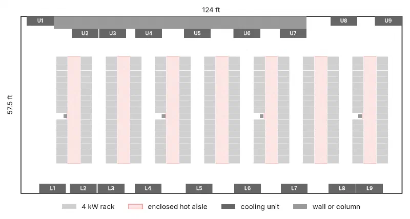
Figure 1
Plan view of the room: 234 racks (light gray) in seven enclosed hot aisle pairs (pale red) and 18 cooling units (dark gray), labeled U1 to U9 along the upper wall and L1 to L9 along the lower wall, numbered from the left
Eighteen cooling units line the two long walls, nine on each. In this paper they are labeled U1 to U9 along the upper wall in Figure 1 and L1 to L9 along the lower wall, numbered from the left. Each supplies about 6,500 CFM, 117,000 CFM in total. L1 supplies 65°F air and the other seventeen 60°F. The racks draw about 114,300 CFM, 98% of what the units supply.
As built, every rack is within the ASHRAE recommended range, and the hottest rack inlet in the room is about 77°F.
Switching Off One Unit
In each case one unit is switched off and the other 17 carry on unchanged, at the same airflow and supply temperature. In the model, the switched-off unit is closed: no air goes in or out of it.
With any one unit off, the racks draw about 114,300 CFM against 110,500 CFM supplied, 103% of supply. That figure is the same whichever unit is off. If the room-level sum were the whole story, all 18 cases would come out the same.
How the Room Was Modeled
Each case was built and solved with CoolSim’s standard model setup, the same one used for customer jobs, and had to pass the same convergence checks before results were taken. In CoolSim, switching units off is set up as variations of one model, and the cases run side by side. The cooling units in the model always supply air at their set temperature, whatever the load; what that leaves out is covered below, under What the Model Does Not Include.
Each rack is judged by the hottest point on its inlet face, against the ASHRAE limits for class A1 equipment [1]: recommended up to 80.6°F, allowable up to 89.6°F. The allowable range is where the equipment is tested to work; the recommended range is where ASHRAE advises keeping it for reliable operation over time.
A solved room of this size never sits perfectly still, so each case was reopened and run on for another 500 iterations, with a snapshot every 25. Reopening a solved case disturbs it for about 110 iterations, so the snapshots taken before its residuals were back under the limits that ended the run are left out. That leaves 16 snapshots of each case. Counts in the tables are the range over them; the figures show each rack’s median.
Results
No rack went over the allowable limit in any of the 18 cases. The hottest rack inlet in any case was 87.4°F, with L8 off.
The recommended limit tells a different story (Figure 2 and Table 1). Six units can be switched off with every rack still within the recommended range: U1, U2, U3, L1, L2 and L3, the three at the left end of each wall. Switching off any of the other twelve puts racks over, from 0 to 1 with U4 off to 17 to 18 with U8 off. The worst are the six units from U6 and L6 to U8 and L8, at 13 to 18 racks over each. The two in the right-hand corners, U9 and L9, do better, at 2 to 6.
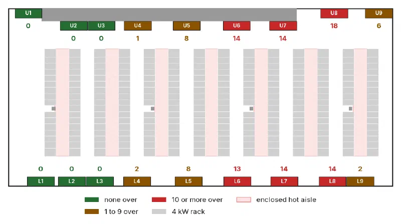
Figure 2
Racks over the recommended limit when each cooling unit alone is switched off (number beside each unit: racks whose median reading over 16 snapshots is over the limit). No rack was over the allowable limit in any case
| Unit off | Wall | Distance from left wall (ft) | Racks over recommended | Hottest rack inlet (°F) |
|---|---|---|---|---|
| none | – | – | 0 | 76.6–76.9 |
| U1 | upper | 6 | 0 | 77.7–78.0 |
| L1 | lower | 10 | 0 | 77.6–77.9 |
| L2 | lower | 20 | 0 | 77.7–77.9 |
| U2 | upper | 21 | 0 | 77.7–77.9 |
| L3 | lower | 29 | 0 | 77.9–78.0 |
| U3 | upper | 30 | 0 | 77.7–78.0 |
| L4 | lower | 41 | 2 | 81.0–81.1 |
| U4 | upper | 42 | 0–1 | 80.6 |
| U5 | upper | 58 | 8 | 83.8 |
| L5 | lower | 58 | 8 | 83.7 |
| U6 | upper | 74 | 14–15 | 84.4–84.5 |
| L6 | lower | 74 | 13 | 85.2–85.4 |
| U7 | upper | 89 | 14–15 | 84.5–84.8 |
| L7 | lower | 89 | 13–14 | 84.4–84.7 |
| L8 | lower | 105 | 14 | 87.3–87.4 |
| U8 | upper | 105 | 17–18 | 86.4–86.7 |
| L9 | lower | 114 | 2 | 81.2 |
| U9 | upper | 120 | 6 | 81.8 |
Table 1
Racks (of 234) whose hottest inlet reading is over the ASHRAE recommended limit (80.6°F) with each unit switched off, in order along the room, and the hottest rack inlet in the room. Ranges are over 16 snapshots of each solved case. No rack was over the allowable limit (89.6°F) in any case
Figure 3 compares the two ends of the same wall. With U1 off, the hottest rack inlet is 77.7 to 78.0°F, about one degree above the room as built. With U8 off, 17 to 18 racks are over the recommended limit, all on the two sides of the cold aisle in front of U8.
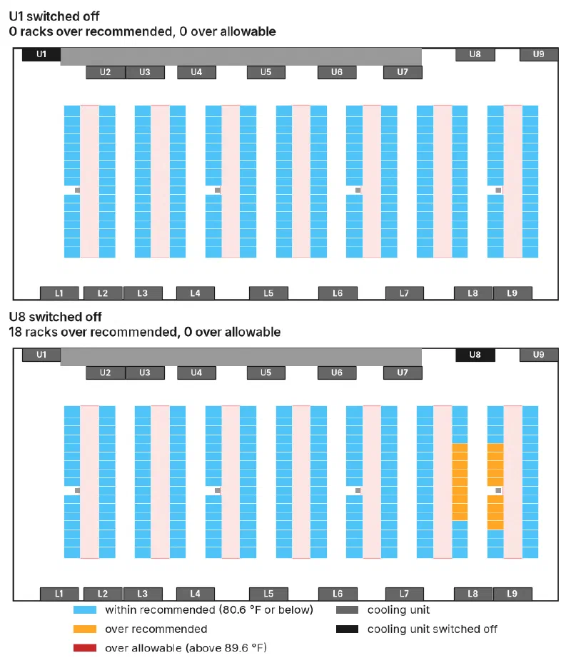
Figure 3
Each rack colored by its hottest inlet reading (median of 16 snapshots) with U1 switched off (top) and with U8 switched off (bottom). The switched-off unit is shown in black
Why: Where the Spare Air Is
Split the room into four equal lengths of 31 ft and count the units and racks in each (Table 2).
| Part of the room (ft from left wall) | Cooling units | Racks | Racks per unit |
|---|---|---|---|
| 0 to 31 | 6 | 50 | 8.3 |
| 31 to 62 | 4 | 67 | 16.8 |
| 62 to 93 | 4 | 50 | 12.5 |
| 93 to 124 | 4 | 67 | 16.8 |
Table 2
Cooling units and racks in each quarter of the room’s length, with all units running
The left quarter has six units for 50 racks. Each of the other three has four, for 50 or 67 racks. Lose a unit in the left quarter and it still has five units for 50 racks, fewer racks per unit than any other part of the room has with every unit running. Lose one anywhere else, and the racks near it draw more air than the units near them supply. The difference comes from air that has already been through a rack, as in WP110.
The room’s spare unit, in other words, sits at the left end. The N+1 margin holds for the room as a whole but not for each part of it.
The quarters are a rough guide, not a rule. The 62 to 93 ft quarter has fewer racks per unit than its neighbors, yet losing any of its four units puts 13 to 15 racks over; and the corner units U9 and L9 do better than their quarter suggests. Air moves between the quarters, and only a full model of the room shows by how much.
Making Up the Lost Air
When a unit goes down, the usual response is to turn up the airflow on the others. Two ways of doing that were tested, each with U8 off and with U6 off, two of the worst cases in Table 1. Both put the room’s total supply back to 117,000 CFM, where it was with every unit running, so the racks again draw 98% of what the units supply:
- Spread it evenly. The other 17 units each supply 6% more air, about 6,900 CFM each.
- Put it next to the lost unit. The two nearest units on the same wall each supply 50% more, 9,750 CFM, and the other 15 carry on unchanged. For U8 these are U7 and U9; for U6, U5 and U7.
| Unit off | No change | Other 17 units, 6% more air each | Two neighbors, 50% more air each |
|---|---|---|---|
| U8 | 17–18 | 11–13 | 6–7 |
| U6 | 14–15 | 8 | 7 |
Table 3
Racks (of 234) over the ASHRAE recommended limit with U8 or U6 switched off, with no change to the other units and with the lost airflow made up in two ways. Both ways restore the room’s total supply to 117,000 CFM. Ranges are over 16 snapshots of each solved case. No rack was over the allowable limit in any case
Both ways helped, and neither was enough. With every unit running, 117,000 CFM kept every rack within the recommended range. With the same 117,000 CFM restored around a switched-off unit, 6 to 13 racks were still over.
Where the extra air went mattered with U8 off and not with U6 off. With U8 off, putting it next to U8 left 6 to 7 racks over, against 11 to 13 when it was spread evenly (Figure 4). With U6 off, the two came out about the same, 7 against 8. In every case the racks still over were in the rows beside the switched-off unit.
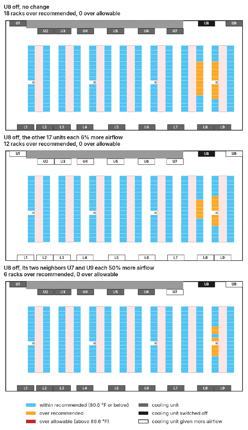
Figure 4
Each rack colored by its hottest inlet reading (median of 16 snapshots) with U8 switched off: with no change (top), with the other 17 units each given 6% more air (middle), and with its neighbors U7 and U9 each given 50% more air (bottom). The switched-off unit is shown in black and the units given more air in outline
There is a cost the model does not count. The cooling units in the model supply air at their set temperature whatever the load, so a unit given more air also removes more heat. With every unit running, each removes about 52 kW on average and the busiest 58 kW. Spread evenly, the busiest of the 17 removed 64 kW. Put next to the lost unit, each of the two neighbors removed 87 to 90 kW, 55 to 60% more than it did with every unit running. Whether a real unit can move half as much air again, and remove that much more heat, depends on its fans and coil, and is a question for its data sheet rather than the model.
What the Model Does Not Include
- Cooling unit capacity. The remaining units hold their supply temperature, which assumes their coils can absorb the lost unit’s share of the heat: 936 kW over 17 units instead of 18, about 6% more each, and up to 60% more for a unit given 50% more air (see Making Up the Lost Air). If they cannot, supply air warms up and the results are a best case.
- Air through a stopped unit. The switched-off unit is modeled as closed. A real unit whose fans stop may let air flow backward through it unless it has a backdraft damper, which could make matters worse.
- Time. Each case is the room after it has settled with the unit off. How fast inlet temperatures climb in the minutes after a unit trips is a separate, time-dependent question not answered here.
- Two units down. Only one unit was switched off at a time. A failure during planned service on another unit was not tested.
- Other rooms. These counts belong to this room and layout. The method carries over.
Conclusions
Each of the 18 cooling units in a 234-rack room with enclosed hot aisles was switched off in turn, and for two of them, two ways of making up the lost air were tested. The results suggest:
- Test every unit, not a sample. A test of the three units at the left end of each wall would have concluded that this room can lose any unit. Twelve of its 18 units put racks over the recommended limit when switched off.
- N+1 for the room is not N+1 everywhere. With any one unit off the room-level sum was the same, 103% of supply, but the results ran from no rack over the recommended limit to 18.
- Look at the racks per unit in each part of the room. This room’s spare capacity is at one end, and a spare unit at one end does not cover the other.
- In this room, no single failure took a rack over the allowable limit. Whether a spell over the recommended limit while a unit is repaired is acceptable is the operator’s call; the model shows which units that call applies to.
- Putting the air back is not the same as putting it where it is needed. Restoring the room’s total airflow left 6 to 13 racks over the recommended limit. Where the extra air went made a difference with one unit off and not with the other, and a neighbor given half as much air again had to remove more than half as much heat again. Test the response to a failure, not only the failure.
References
- ASHRAE Technical Committee 9.9, Thermal Guidelines for Data Processing Environments, 5th ed., ASHRAE, 2021.
- WP108: Building Redundancy into a Data Center Cooling System, CoolSim, 2011.
- WP110: Adding AI Racks to an Air-Cooled Data Center, CoolSim, 2026.