Introduction
Many data centers supply colder air than their racks need. Cold supply air is a margin against hot spots, but it is not free: the cooling plant works harder to make it, and a rack that takes in air below the ASHRAE recommended range gains nothing from it. The usual answer is to raise the supply air temperature. The question is how far. A room that is over-cooled on average can still have a few racks near the top of the range, and those racks set the limit.
An earlier CoolSim paper, WP109 [2], asked of a telecommunications room: “Could the supply temperatures be increased?” It found that “at least half of the racks have inlet temperatures that are too cold.” In this paper, CoolSim is used to raise the supply air in a 234-rack room in 4°F steps, from 60°F to 72°F, first with the airflow as built and then with the airflow moved away from the end of the room that has more cooling than it needs.
Problem Description
The room is the one studied in WP110 [3] and WP111 [4]: 124 ft by 57.5 ft, with 234 racks at 4 kW each, 936 kW in total, in seven enclosed hot aisle pairs. Eighteen cooling units line the two long walls, labeled U1 to U9 along the upper wall and L1 to L9 along the lower wall, numbered from the left. Each supplies about 6,500 CFM, 117,000 CFM in total, and the racks draw about 114,300 CFM.
As built, L1 supplies 65°F air and the other seventeen 60°F. The hottest rack inlet in the room is about 77°F, 3 to 4°F under the recommended limit.
WP111 found that this room’s spare cooling is at its left end. Any one of the six units there, U1 to U3 and L1 to L3, can be switched off with no rack going over the recommended limit, and the left quarter of the room has six units for 50 racks where each other quarter has four, for 50 or 67.
The Cases
Four supply temperatures were tested: 60°F (as built), 64°F, 68°F and 72°F. In every case L1 stays 5°F warmer than the rest, as built.
Each supply temperature was tested with three ways of spreading the same 117,000 CFM among the units:
- As built. Every unit supplies about 6,500 CFM.
- Shifted 25%. The six units at the left end each supply 25% less air, about 4,900 CFM, and the other twelve 12.5% more, about 7,300 CFM (Figure 1).
- Shifted 40%. The same six supply 40% less, 3,900 CFM, and the other twelve 20% more, 7,800 CFM.
That makes twelve cases.
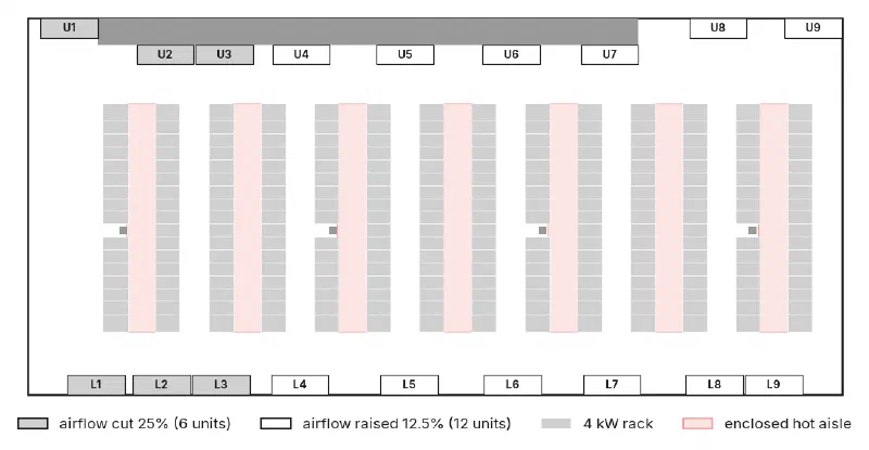
Figure 1
The 25% airflow shift: the six units at the left end of the room (light gray) each supply 25% less air and the other twelve (outlined) 12.5% more, so the total is unchanged. The 40% shift uses the same units, 40% less and 20% more
How the Room Was Modeled
Each case was built and solved with CoolSim’s standard model setup, the same one used for customer jobs, and had to pass the same convergence checks before results were taken. The cooling units in the model always supply air at their set temperature, whatever the load; what that leaves out is covered below, under What the Model Does Not Include.
Racks are judged against the ASHRAE limits for class A1 equipment [1]. At the top, each rack is judged by the hottest point on its inlet face: recommended up to 80.6°F, allowable up to 89.6°F. At the bottom, each rack is judged by the average temperature across its inlet face, against the recommended minimum of 64.4°F. A rack below that minimum but above the allowable minimum, 59°F, is within its rating; it is being given cooling it does not need. No rack in any case took in air below 59°F.
A solved room of this size never sits perfectly still, so each case was reopened and run on for another 500 iterations, with a snapshot every 25. Reopening a solved case disturbs it for about 110 iterations, so the snapshots taken before its residuals were back under the limits that ended the run are left out. That leaves 15 or 16 snapshots of each case. Counts in the tables are the range over them; the maps show each rack’s median.
Results
At 60°F: over-cooled, with little room at the top
As built, 152 to 157 of the 234 racks, about two in three, take in air whose average is below 64.4°F (Table 3). At the same time the hottest rack inlet is 76.6 to 76.9°F, about 4°F from the recommended limit (Table 2). Shifting the airflow does not change the first number much, 150 to 173 racks: at 60°F the supply is too cold for most racks whatever the balance.
Raising the supply alone
At 64°F no rack’s average inlet is below 64.4°F, with any of the three balances. But with the airflow as built, 4 to 8 racks go over the recommended limit, and the hottest rack inlet reaches 81.1 to 81.4°F (Tables 1 and 2, Figure 2). At 68°F it is 51 to 56 racks, and at 72°F 97 to 102, with 3 to 5 of them over the allowable limit as well. Each 4°F on the supply adds a little more than 4°F to the hottest rack inlet.
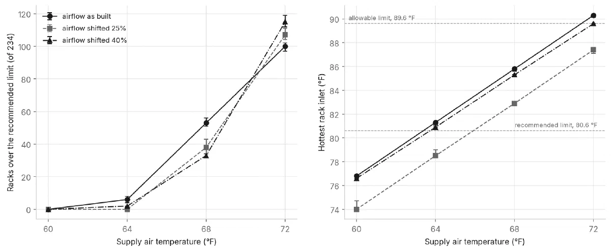
Figure 2
Racks over the ASHRAE recommended limit (left) and hottest rack inlet (right) against supply air temperature, for each airflow balance. Points are the median of 15 or 16 snapshots; bars span the lowest and highest
Balance the air first, then raise the supply
With the airflow shifted 25%, every rack stays within the recommended range at 64°F. The hottest rack inlet is 78.4 to 79.0°F, and no rack’s average inlet is below 64.4°F. The shift alone takes about 3°F off the hottest rack inlet at every supply temperature tested.
Shifting 40% does less, not more. At 64°F, 2 racks are over the recommended limit, and the hottest inlet is 80.9 to 81.0°F, about 2°F warmer than with the 25% shift.
Figure 3 shows where. As built, the racks over the limit at 64°F are at the right end of the room. The 25% shift clears them, and the hottest rack in the room moves from the right end to the left quarter. The 40% shift goes past that point: the right end stays clear, and racks at the left end, which now has less air, go over instead.

Figure 3
Each rack colored by its hottest inlet reading (median of 15 or 16 snapshots) at 64°F supply: with the airflow as built (top), shifted 25% (middle) and shifted 40% (bottom). Units whose airflow was cut are shown in light gray, and units given more air in outline
Above 64°F
No balance tested keeps every rack within the recommended range at 68°F or 72°F. At 72°F the shifts lower the hottest inlet but spread the heat. With the 25% shift every rack stays within the allowable range, the hottest at 87.1 to 87.4°F, where the room as built has 3 to 5 racks over it; but 104 to 111 racks are over the recommended limit, against 97 to 102 as built.
| Supply air | Airflow as built | Airflow shifted 25% | Airflow shifted 40% |
|---|---|---|---|
| 60°F | 0 | 0 | 0 |
| 64°F | 4–8 | 0 | 2 |
| 68°F | 51–56 | 34–43 | 32–34 |
| 72°F | 97–102 | 104–111 | 112–119 |
Table 1
Racks (of 234) whose hottest inlet reading is over the ASHRAE recommended limit (80.6°F). Ranges are over 15 or 16 snapshots of each solved case. Racks over the allowable limit (89.6°F): 3 to 5 at 72°F as built, 0 to 1 at 72°F shifted 40%, none in any other case
| Supply air | Airflow as built | Airflow shifted 25% | Airflow shifted 40% |
|---|---|---|---|
| 60°F | 76.6–76.9 | 74.0–74.7 | 76.5–76.6 |
| 64°F | 81.1–81.4 | 78.4–79.0 | 80.9–81.0 |
| 68°F | 85.6–85.9 | 82.7–83.1 | 85.2–85.3 |
| 72°F | 90.1–90.3 | 87.1–87.4 | 89.5–89.6 |
Table 2
Hottest rack inlet in the room (°F). Ranges are over 15 or 16 snapshots of each solved case
| Supply air | Airflow as built | Airflow shifted 25% | Airflow shifted 40% |
|---|---|---|---|
| 60°F | 152–157 | 165–173 | 150–154 |
| 64°F | 0 | 0 | 0 |
| 68°F | 0 | 0 | 0 |
| 72°F | 0 | 0 | 0 |
Table 3
Racks (of 234) whose average inlet temperature is below the ASHRAE recommended minimum (64.4°F). Ranges are over 15 or 16 snapshots of each solved case
A note on 64°F
A supply of 64°F is itself 0.4°F below the recommended minimum. At 64°F, about 100 racks in each balance have a spot on their inlet face less than 0.4°F above the supply air, and so below 64.4°F, although no rack’s average is. A supply of 65°F would clear those spots. It was not tested; reading between 64°F and 68°F in Table 2, the hottest inlet with the 25% shift would be about 80°F, close to the recommended limit.
Why: Where the Air Goes
Table 4 splits the room into four equal lengths of 31 ft, as in WP111, and shows the airflow the units in each supply, with what that comes to per rack. The racks draw about 490 CFM each.
| Part of the room (ft from left wall) | Racks | As built | Shifted 25% | Shifted 40% |
|---|---|---|---|---|
| 0 to 31 | 50 | 39,000 (780) | 29,250 (585) | 23,400 (468) |
| 31 to 62 | 67 | 26,000 (388) | 29,250 (437) | 31,200 (466) |
| 62 to 93 | 50 | 26,000 (520) | 29,250 (585) | 31,200 (624) |
| 93 to 124 | 67 | 26,000 (388) | 29,250 (437) | 31,200 (466) |
Table 4
Airflow (CFM) supplied by the cooling units in each quarter of the room’s length, and in brackets per rack in that quarter
As built, the left quarter gets twice as much air per rack as the two 67-rack quarters. The 25% shift gives every quarter the same airflow. The 40% shift goes further and gives the left quarter and the two 67-rack quarters about the same airflow per rack, which on these sums looks like the better balance. The model says otherwise.
At 68°F, where every balance has racks over the limit, the room as built has them at the right end: 0, 5, 22 and 26 in the four quarters from left to right (median of 16 snapshots). The 25% shift spreads them along the room, 8, 15, 10 and 4. The 40% shift moves them to the left, 14, 14, 5 and 0. Air moves between the quarters, and the sums cannot say how much; the model can.
What It Costs
The shift moves heat as well as air. The cooling units in the model hold their supply temperature, so a unit given more air also removes more heat. The busiest unit removes 58 kW as built, 62 kW with the 25% shift and 66 kW with the 40% shift; the least loaded, 39, 32 and 28 kW. The room’s total is 937 kW in every case. Whether the busiest unit can do that, at the warmer return air a warmer supply brings, is a question for its data sheet.
Fan power is not in the model. Fan power rises roughly with the cube of airflow, so moving air from six units to twelve raises the room’s fan power for the same total airflow: by about 9% for the 25% shift and 22% for the 40% shift, if every unit follows that rule. That is arithmetic, not a model result, and it counts against whatever the warmer supply saves at the plant.
A shift like this also needs cooling units whose fan speed can be set one by one.
What the Model Does Not Include
- Cooling unit capacity. Every unit holds its supply temperature, which assumes its coil can absorb whatever heat reaches it: up to 66 kW for the busiest unit with the 40% shift (see What It Costs). If it cannot, supply air warms up and the results are a best case.
- Fan power. The fan-power figures above come from the fan laws, not the model.
- Humidity. Humidity and dew point are not modeled. ASHRAE’s recommended range has humidity limits as well as temperature limits [1].
- The plant. How much energy a warmer supply saves depends on the chillers, the economizer hours and the climate, none of which are in a room model. This paper does not estimate it.
- Other rooms. These counts belong to this room and layout. The method carries over.
Conclusions
The supply air temperature in a 234-rack room with enclosed hot aisles was raised from 60°F to 72°F in 4°F steps, with the airflow as built and with two shifts of airflow away from the end of the room that had more than it needed. The results suggest:
- Over-cooled on average is not the same as margin everywhere. At 60°F two racks in three were below the recommended minimum while the hottest was within 4°F of the recommended limit.
- Raising the supply alone ran out of margin at the first step. At 64°F, 4 to 8 racks went over the recommended limit with the airflow as built.
- Balance the air first, then raise the supply. Moving 25% of the airflow from the six units at the left end to the other twelve took about 3°F off the hottest rack inlet, and at 64°F every rack stayed within the recommended range.
- More shift is not better. A 40% shift looked like the better balance by airflow per rack, yet its hottest rack inlet was about 2°F warmer than with the 25% shift at every supply temperature, and its hot spots moved to the other end of the room.
- Count the costs. In this room the shift raised the busiest unit’s load from 58 to 62 kW and, by the fan laws, the fan power by about 9%. Check both before making the change.
References
- ASHRAE Technical Committee 9.9, Thermal Guidelines for Data Processing Environments, 5th ed., ASHRAE, 2021.
- WP109: Reducing the Annual Cost of a Telecommunications Data Center, CoolSim, 2011.
- WP110: Adding AI Racks to an Air-Cooled Data Center, CoolSim, 2026.
- WP111: Which Cooling Unit Can You Afford to Lose?, CoolSim, 2026.