CoolSim Overview
CoolSim 5 is the most effective data center airflow modeling tool on the market today. A 3D graphical user interface enables quick and easy construction of a data center model. The airflow and temperature distribution are then calculated using computational fluid dynamics (CFD). Finally, comprehensive reports, graphics, and animations are generated automatically and can be viewed from CoolSim or using any internet connected browser.
Key Features
Simple user interface with familiar terms
CoolSim was designed with ease of use as a cornerstone of the application. All objects can be simply dragged and dropped into the 3D environment. Libraries of common objects are available for users to insert. Additionally, users can create their own objects and add them to the library system for future use on other models. Online training allows users to progress at their own pace.
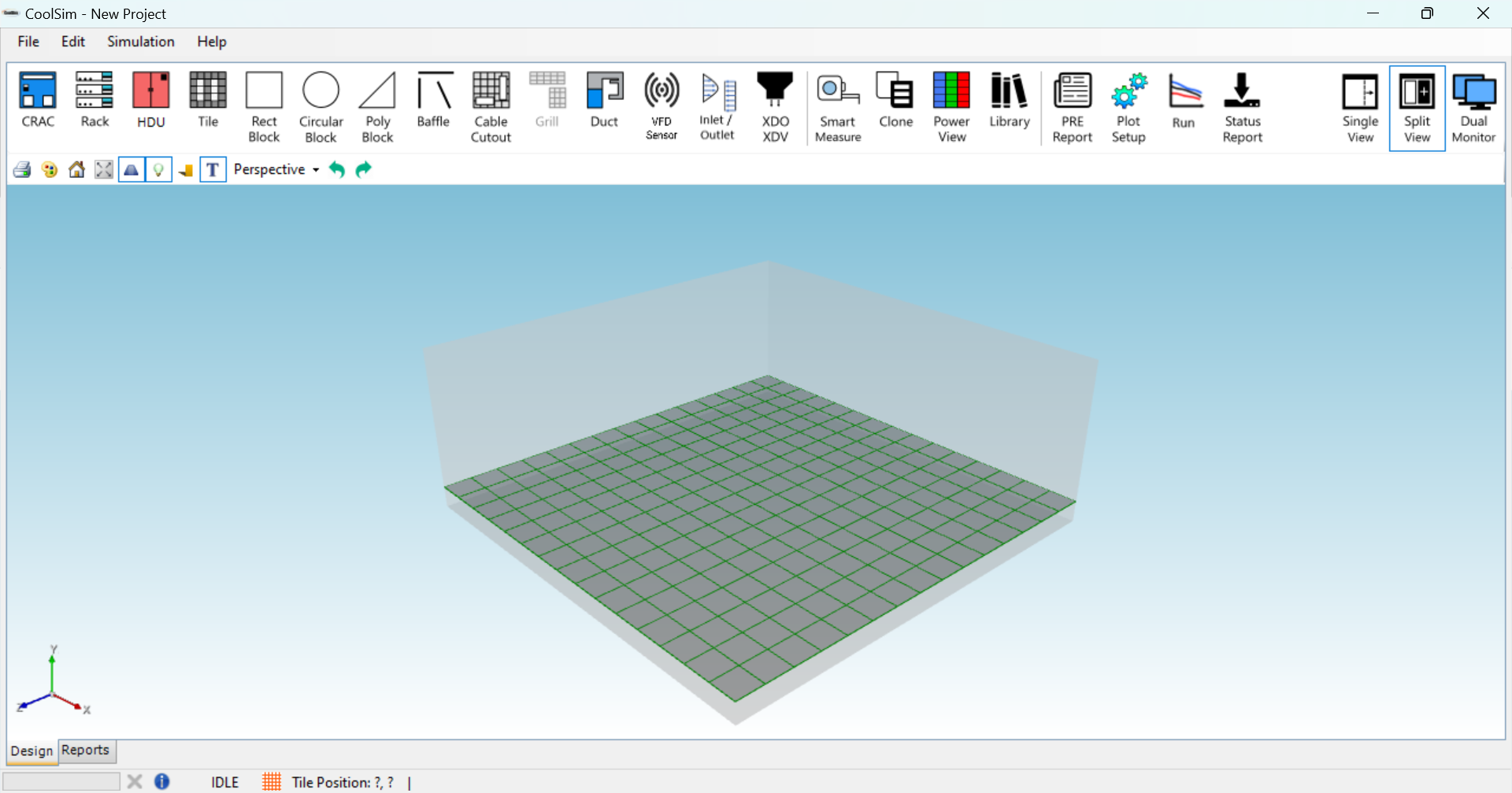
CoolSim model at start-up
Ansys Technology in a Pay-As-You-Go Model
With CoolSim, model building is performed on a local PC and the CFD meshing, solving, and postprocessing are done on a cloud based high-performance computing cluster. As an Ansys Technology Partner, our remote simulation facility (RSF) uses world-leading simulation technology, providing you with the best meshing, solving, and post-processing technology in the industry without needing to commit to costly annual licenses.
Our flexible licensing options accommodate budgets for both short-term, project-oriented timelines and year-round usage.
Superior End User Support
All customer simulations are monitored for possible failure. Support engineers can query the server log files for problems, fix them, and resubmit jobs for further processing. This approach significantly improves the CoolSim user experience and greatly reduces simulation turn-around time.
Comprehensive Output Reports
The Data Center Output Report delivered by CoolSim is a key distinguishing feature of the software. Generated automatically, it includes numerical reports of the flow and temperature fields for all of the equipment in the room, as well as graphics and animations.
The 3D results files can be manipulated with the mouse to alter the view or zoom into certain regions for more careful inspection.
Special keyboard commands allow for the output of high-resolution image files for hardcopy production. The HTML report can be shared via URL, or exported into PowerPoint or Excel, making it easier for users to share the results.
CoolSim Modeling Capabilities
Raised / Non-Raised Floor Designs
Any type of data center room configuration can be built in CoolSim, including:
- Raised-floor and ceiling return plenums
- Rooftop cooling (RTUs)
- Fan wall designs
- Angled or round walls
- Obstructions like overhead/underfloor cable trays or building pylons
Cooling Systems
CoolSim supports various cooling methods including:
- Constant supply temperature
- Linear and non-linear cooling capacity controlled by thermostats on the supply and/or return
- Variable Frequency Drive (VFD) controlled by temperature or pressure differential
A catalog of CRAC units are available for use in the equipment library, including downflow, upflow, and in-row units. Custom units can be built by the user or by request to match your equipment.
Ducted Designs
CoolSim offers a ducting tool that allows the placement of ducts and diffusers in any section of the room. Diffusers can be adjusted to balance flow throughout the room.
Custom IT Rack Configurations
Individual servers can be configured in IT racks at the 1U level. Each server can be adjusted with power load and expected temperature rise. Missing blanking panels can be modeled using the rack “gap” feature and defined at the rack unit level.
CRAC Parameter Variation (CPV) Analysis
CoolSim users can submit up to 4 variations of CRAC parameters concurrently. CPV parameters include power state (on/off), air flow rate, and supply air temperature. This feature enables simulated failure modes and effects analysis (FMEA) for mission-critical operations.
External Flow
Since CoolSim 5, users have the ability to set up and model exterior wind direction and temperature. Chillers, generators, and heat exchangers can be added to building rooftops or equipment yards to study the effects of various wind conditions on heat rejection performance. This allows campus designers to experiment with equipment placement and spacing prior to physical deployment.
General Purpose Inlets and Outlets
General purpose inlets/outlets can be added to the model allowing users to model any kind of air inlets or outlets in a room. Control parameters include mass flow rate, temperature, and angle of flow.
Summary
CoolSim is the only offering in the data center modeling market that offers a strong combination of ease-of-use, effectiveness, and cost. Applied Math Modeling, Inc. is committed to supporting the data center design-and-build segment with nearly 20 years of experience in this field.